naxdiscover.blogg.se

Zmm lathe manual
Zmm lathe manual


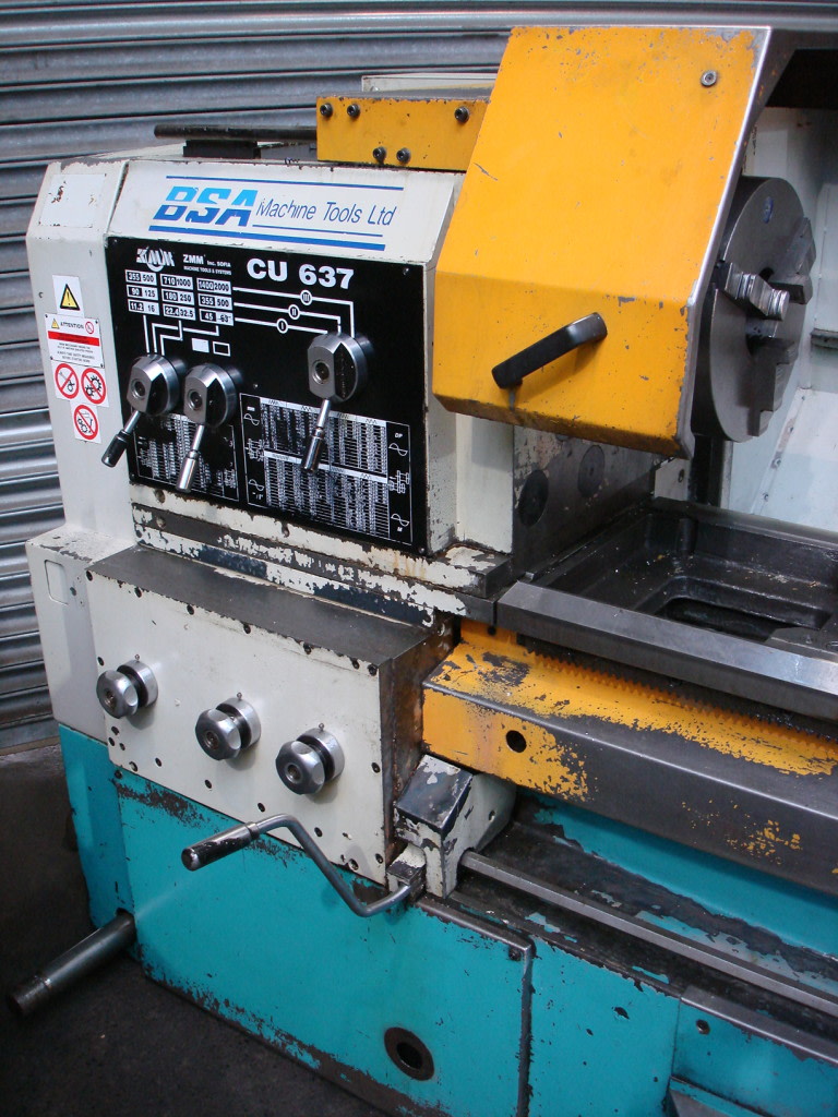
Warning: Changing the spindle speed ONLY after stopping the spindle. Starting and stopping the spindle for rotation in the forward or reverse direction is performed by the handle 22 of Fig. The color against the background of the required revolving stage is set opposite the arrow on the plate. 4-1, is equipped with three color indications (green, red and blue) fig. 4-4 is positioned against the arrow on the plate. Note: With the CU500MT, the sector with the required revolutions of Fig. 4-2, having two fixed positions, the pointer is set in the direction of the corresponding sector. The sector of the disk in which the required revolutions are located is set to the left or right of the vertical line, depending on where the fixed position of the disk is. 4-5, located on the front side of the gearbox and controlled by the handle 24 of Fig. The choice of the speed step for all models is made by the handles 24, 25 and 26. Speed \u200b\u200bsteps for each specific machine model are shown in Figures 4-3, 4-4, 4-5 and 4-6.

zmm lathe manual

The universal turning machines СU400 are equipped with 21 direct and 11 reverse speed steps of the spindle speed.

  • Button to turn accelerated movement on and offĪ brief description of the main components of the machine CU-500 (SU-500) Select spindle speed.
  • #ZMM LATHE MANUAL MANUAL#

    Handwheel for manual movement of pintles.Nonius to account for longitudinal movement.Handwheel for manually moving the upper caliper.Control lever for longitudinal and lateral movements.

    zmm lathe manual

  • Handle for turning on and off the split nut.
  • Handle for shifting movement to the drive shaft or drive screw.
  • Handle for selecting feed or thread steps.
  • Handle for selecting ranges of reverse order.
  • Handle for selecting “normal” or “increased” thread pitch and feeds.
  • Control lever for switching in the "forward" and "reverse" direction of rotation or for switching off the spindle rotation.
  • Handle for switching to the "left" and "right" threads.
  • Location of CU-500 Machine Controls List of CU-500 Lathe Controls (SU-500) Photo CU-500 Lathe Location of components and controls of the CU-500 lathe (SU-500) General view of the screw-cutting lathe CU-500 (SU-500)
  • CU 500RD - a frequency converter integrated in the main drive - stepless spindle speed control.
  • CU 500MT - enlarged hole in the spindle up to Ø 100 mm.
  • CU 500M - enlarged hole in the spindle up to Ø 72 mm.
  • The diameter of the front spindle bearing is Ø 100 mm.
  • Cu 500 - base model Spindle bore Ø 62 mm.
  • The mechanisms in the feed box are lubricated automatically by a piston oil pump and through spraying. The spindle system, gear transmissions and other mechanisms in the gearbox are lubricated automatically through a gear oil pump and by spraying. The speed steps of the machine are indicated in the passport in Figures 4-3, 4-4, 4-5 and 4-6.Īccording to the customer’s order, the machine can be delivered with the spindle end according to DIN55027 / ISO702-III or according to USAS B-5.9-D1 / ISO702-II (Camlock). The SU500 universal lathe is equipped with 21 direct and 11 reverse speed spindle speed steps. The principle of operation and design features of the machine

    zmm lathe manual

    Using a cone ruler (option), you can process conical surfaces. Machined parts are mounted in centers or chucks. Appointment, scopeĬU-500 turning screw cutting machine (SU-500) is designed for various turning operations and cutting metric, modular, inch and pitch threads. CU-500 (SU-500) Machine universal screw-cutting. CU 500 Lathe Manufacturer - Enterprise JSC "ZMM - Sliven" (ZMM-Sliven), which is part of the machine-tool holding ZMM "Bulgaria Holding (Zmm-Bulgaria Holding Ltd.)"- the largest manufacturer of universal turning machines in Europe.


    Zmm lathe manual